OUTPUT TRANSFORMERS FOR 13E1 POWER AMP

I needed a transformer that can be used with either a 4 or 8 ohm speaker, has Ra-a (resistance that the output tubes see) = about 8K and has taps for cathode feedback. I developed an excel spreadsheet that allows for a lot of trial and error and came up with the winding diagram shown below.
The primary and secondary windings are fully interleaved. There are 16 primary windings, indicated by the thin lines on the diagram below. These are connected together as shown to make a total of 2576 turns.
There are 4 layers of secondary windings; the first 3 (A-B, C-D, E-F) have 60 turns each, the 4th one has 3 windings of 20 turns each (G-H, I-J, K-L).
Starting at anode2, two primary layers are wound, followed by secondary winding A-B, then 3 more primary windings, then a cathode feedback winding, then a 2nd secondary winding C-D, and so on.
This is an extremely laborious process, because after each winding, I saturate the winding with disgusting transformer varnish, followed by a wrap of .05mm kapton tape, and a wrap of thick (.38mm) Nomex insulating paper if called for. Note that the diagram says .63mm - this is a mistake.
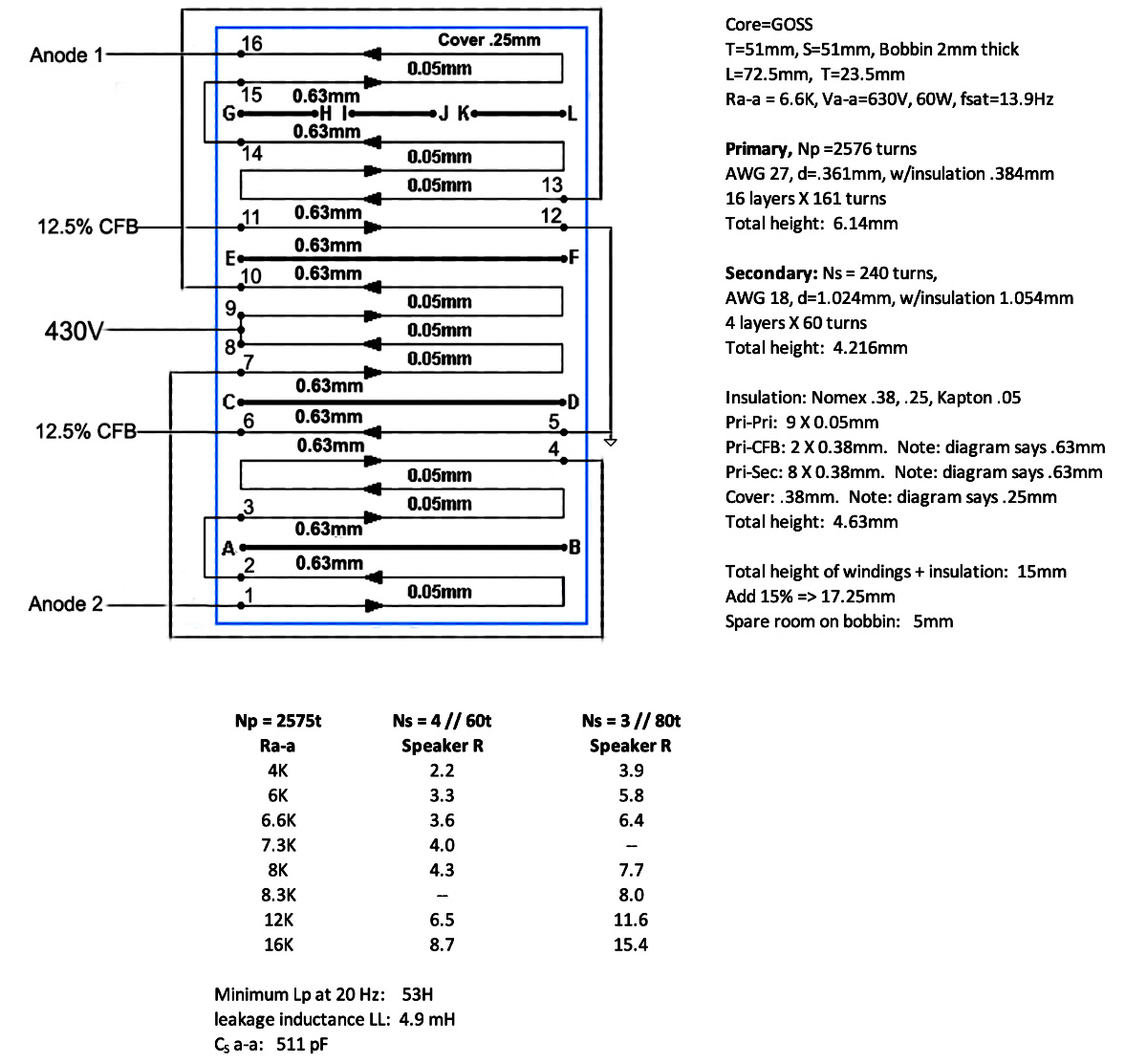
The total number of primary windings is 2576 turns. Each secondary winding has 60 turns. The top secondary winding is divided into 3 windings of 20 turns each. There are 2 choices for the number of secondary turns - this is the brilliant part, definitely not thought up by me.
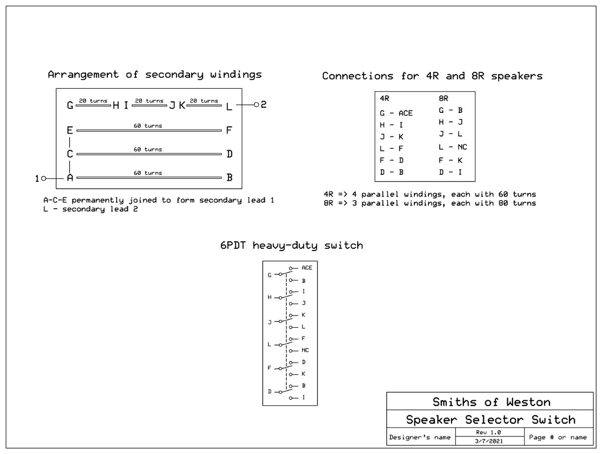
Option 1: G-H, I-J, and K-L are tied together in series to make a 4th winding of 60 turns, then all 4 secondary windings are tied together in parallel. This makes a very heavy-duty secondary winding of 60 turns. The turns ratio TR = 2576/60 = 42.9. The impedance ratio is the square of the turns ratio = 1843.
Option 2: A-B is placed in series with G-H to make a winding of 80 turns. C-D is in series with I-J, and E-F is placed in series with K-L. This makes 3 secondary windings of 80 turns. These are placed in parallel, to make a slightly less heavy-duty secondary winding of 80 turns. This gives a turns ratio of 32.2, and an impedance ratio of 1037.
The calculations are shown above. With a 4 ohm speaker, Ra-a is about 7.3K. With an 8 ohm speaker, Ra-a is around 8.3K. Close enough. No speakers are even remotely close to whatever impedance they are rated at.
The above connections can be performed with a 6-pole, 2-position switch, shown below.
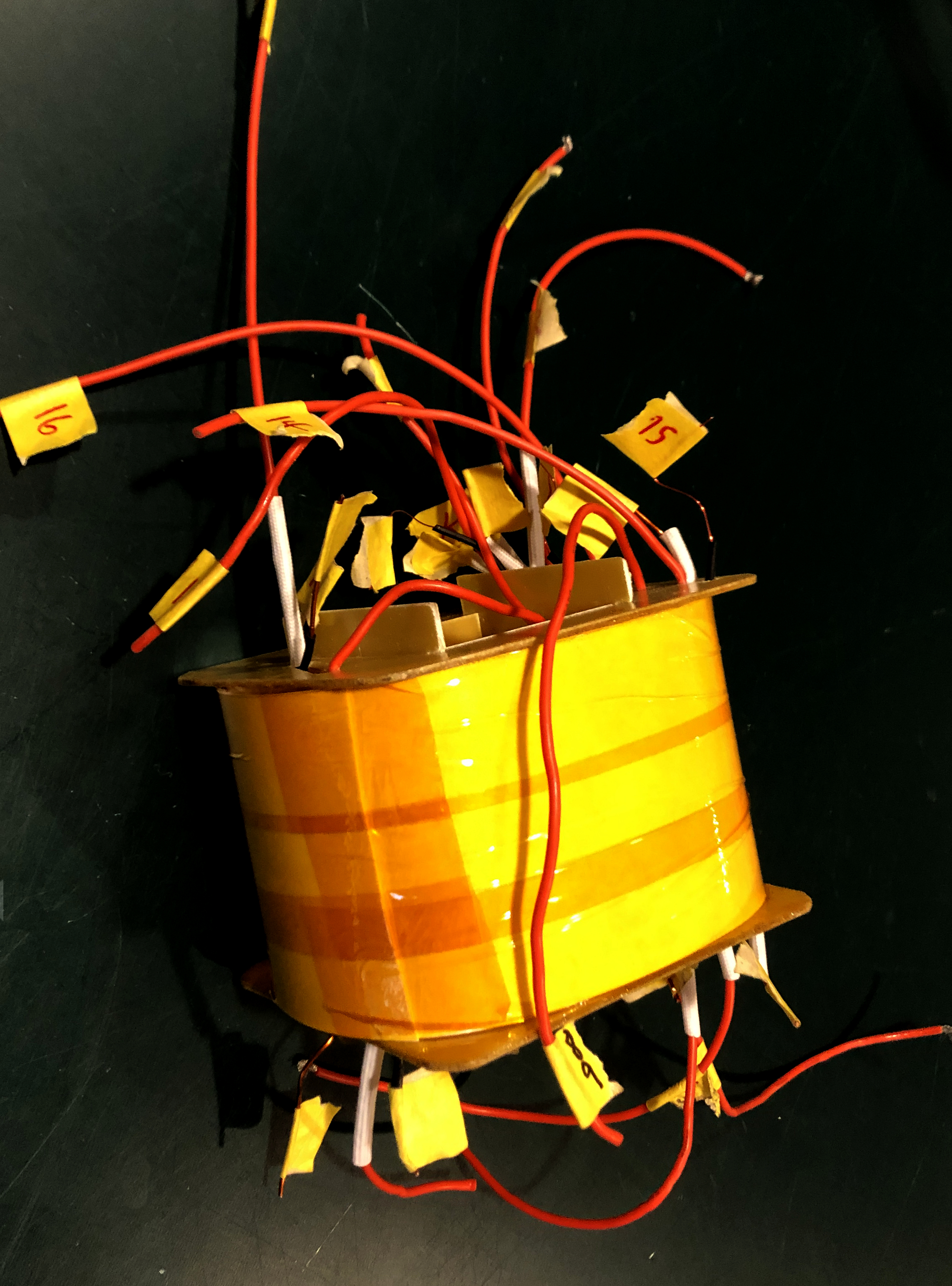
Below is the completely wound bobbin with wires sticking everywhere. Most of the wires will be attached to the switch above. It's now time to address the laminations.
The laminations I bought are high-quality, M6 GOSS iron laminations. It is necessary to determine the permeability of these laminations. The following jig shown below was set up to measure the permeability of the laminations. I made a bobbin with a tongue width a=51mm, just like the output transformer, and stack height S = 20mm, to give a core area A=10.2cm2. I wound 250 turns (N=250) of the same wire I used on the output transformer. Finally, I put a 100R resistor in series with the coil and hooked it up to my variac. I made measurements of voltage across the resistor (Vr) and voltage across the coil (Vcoil) as the variac voltage was adjusted from 1V to around 60-70V.
The following calculations were done:
I = Vr / 100
XL = Vcoil / I; this is the reactance of the coil
L = XL / 2pif, where f = 60Hz.
Now, inductance is L = N2AμR*μO/LMT. where uO = 4pi E-7 and LMT = length of magnetic turn, in this case LMT = 222mm.
So μR can be calculated from this formula, and what better way to do this than with an excel spreadsheet. I varied the variac and made measurements until I found the maximum μR, and the relevant data from the spreadsheet is shown below.

Note that the maximum μR is over 14000. This is too high, so that a partial gap needs to be put in. This is done by not fully interleaving the laminations, but interleaving them maybe 8 at a time, meaning that 8 go one way, 8 the opposite way, etc. The goal is to reduce the μR to around 4000 to 5000.
I inserted the laminations 8 at a time; this is shown below.
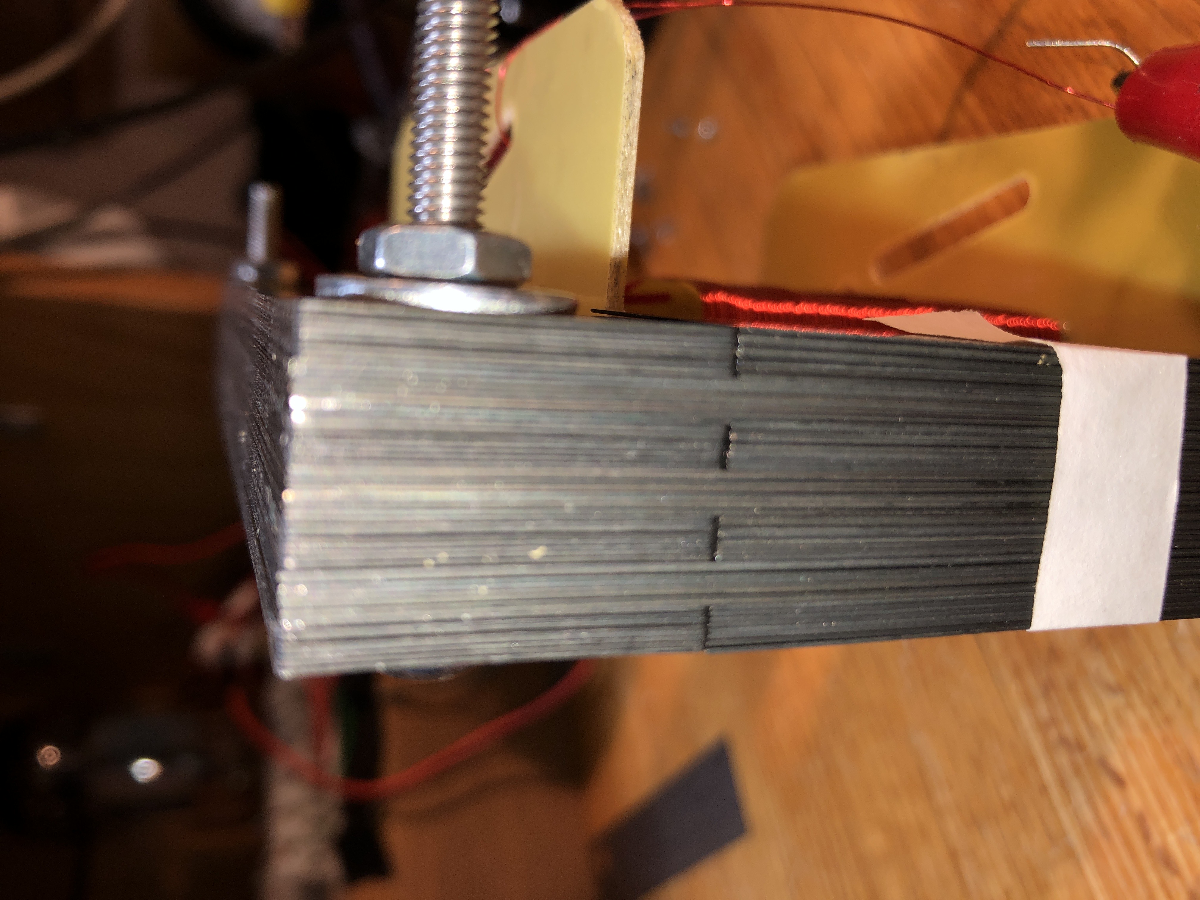
Varying the variac as above to find the maximum μR yielded the following results:

The μR is still too large. I'll try 12 laminations at a time.