13E1 AMP POWER SUPPLY CHOKE
In previous amplifiers, I used "capacitor multipliers" to smooth the power supply ripple. These required fairly fragile MOSFET circuits which I blew up more times than I can count. For this amplifier, I have decided to replace the elegant, fragile silicon solution with a manly IRON solution - a big heavy choke. Now that Smith Iron, a subsidiary of Smiths of Weston, is up and running, LOL, I will design and wind these chokes myself.
The amp will be pulling a little less than .7A from the power supply. I tried making a choke from recovered laminations from some old rusty transformers I had lying around, but they were pathetic. The permeability of the laminations must have been in the low hundreds; this is contrasted with the brand new laminations that I bought, which have permeability in the thousands, and can generate much greater inductance before saturating.
I will be using one choke per channel, so each choke will handle .35A DC.
The design parameters are shown below. I have procured (off eBay) some 29mm bobbins, and have bought some nice American-made laminations. The stack height will be 40mm.
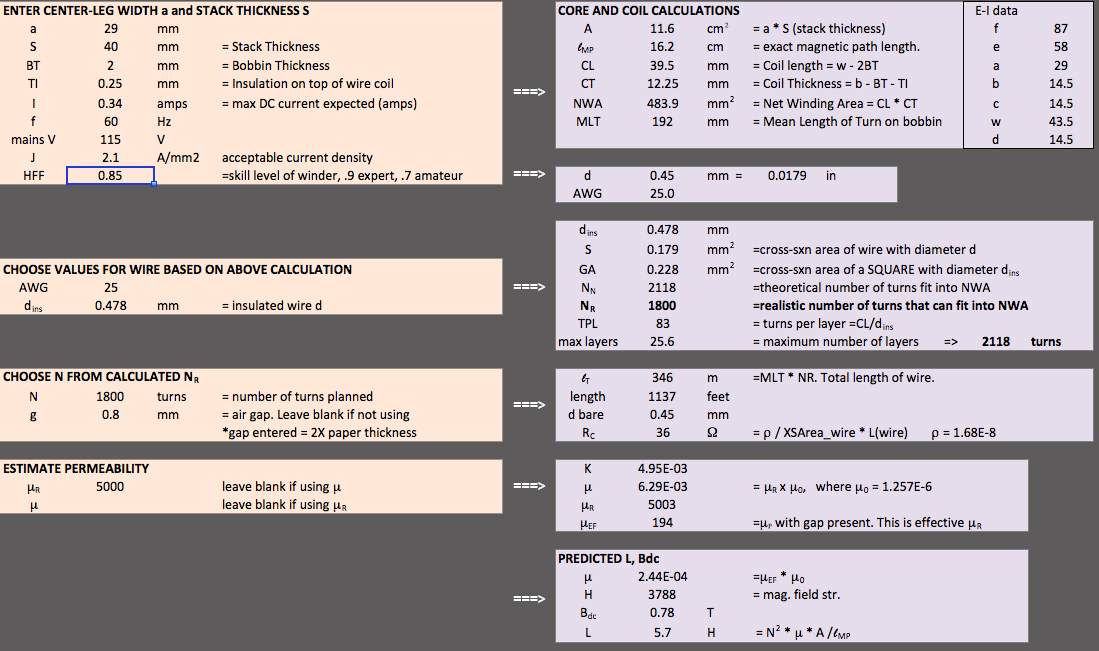
So, with a gap of .8mm (4 sheets of paper), I can get 5.7H with a flux density of only .78T. Perfect. There will be 1137 feet of 25AWG magnet wire, for a total resistance of 36R.
I managed to get 1430 turns on the bobbin. The measured resistance of the windings is 26 ohms. The following table shows the calculated inductances and flux densities for various gaps. The flux density should be less than 1.5 for GOSS laminations, to avoid saturation of the core, and massive deterioration in performance.
| gap(mm) | L (H) | flux density (T) | 0.2 | 12.8 | 2.2 |
| 0.4 | 6.9 | 1.2 |
| 0.6 | 4.8 | 0.81 |
Below is the finished choke, pre-varnish, ready for testing. All the E laminations are on one side and all the I laminations are on the other side. I will try different gaps between the E's and the I's. The strips of paper can be seen between the E and I laminations. A single piece of laser paper is .1mm thick. The actual gap is 2 X the paper thickness, so 4 pieces of paper gives a gap of 0.8mm.
I measured the inductance of the choke, with varying gaps with just an 120Hz AC voltage from a signal generator. There is no DC current, and the AC voltage is only about 2-3V RMS, but it should give a general idea of what the inductance will be. The results are as follows:
| gap(mm) | L (H) |
| 0.0 | 258 |
| 0.2 | 24.8 |
| 0.4 | 13 |
| 0.6 | 8.8 |
| 0.8 | 6.7 |
| 0.9 | 5.9 |
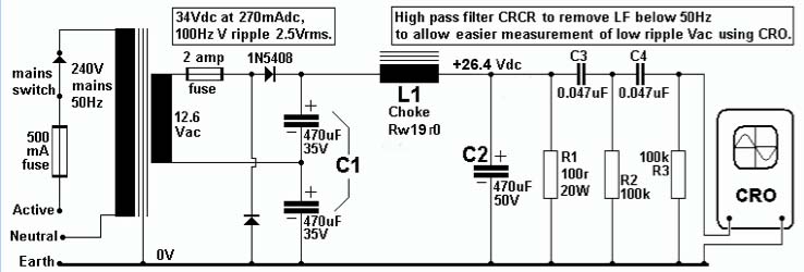
The circuit below is a clever circuit created by Patrick Turner of turneraudio.co.au. It creates ripple equivalent to that coming out of a large power transformer, but at 26-27V rather than 400-500, so testing of chokes is much safer. When I tested my choke, I got a beautiful clean DC output and the ripple was unmeasurable, using either a Fluke multimeter or my oscilloscope. I assume the ripple is less than 10mV with .8mm gap, so I'm going to call it a day