AUDIO OUTPUT TRANSFORMERS
An audio transformer can be modeled as below. Image courtesy of Igor Popovich
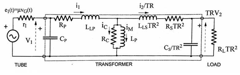
ri = anode resistance of output tube
Cp = capacitance of the primary winding
Rp = resistance of primary windings
LLP = leakage inductance of the primary winding
Rc = core power losses, due to eddy currents and hysteresis
Lp = primary inductance
LLSTR2 = leakage inductance of secondary reflected to the primary side. TR = turns ratio
RsTR2 = secondary resistance reflected to the primary side
Cs/TR2 = parasitic capaticance of secondary reflected to the primary side
The parallel combination of Rc and Lp is the transformer itself. Now, this is a very complicated model to analyze, so it will be analyzed for the Low frequency model, midfrequency model, and HF model.
MID-FREQUENCY MODEL
At mid-frequencies (100 - 5000Hz), all inductances and capacitances can be pretty much ignored, so you're left with just a simple voltage divider:
Vo = RLTR2 / (ri + Rp + RsTR2 + RLTR2).
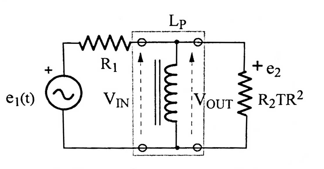
LOW FREQUENCY MODEL
At low frequencies (200Hz to 5kHz) the inductances and capacitances can be ignored except for Lp. So you're left with the following simplified model:
where R1 = rI + Rp and R2 = (Rs + RL)TR2
Now the frequency where the output voltage drops by 1/√2 relative to the midband gain is the -3dB frequency fL. This frequency is determined by the following:
fL = [R1R2TR2 / (R1 + R2TR2)]/2πLp, or more simply
fL = (R1 ∥ R2TR2) / 2πLp ∥ means "parallel with"
Or, even more simply:
fL = RPAR / 2πLp, where RPAR = R1∥R2TR2
Remembering that R2TR2 = primary impedance of XFMR, also known as ZP:
RPAR = R1 ∥ ZP. Now, rI >> Rp, so Rp can be ignored (it's usually less than 100). Thus:
RPAR = rI ∥ ZP
So, finally;
You want fL as low as possible, so you want LP above a certain minimum. Rearranging the above, gives:
LPMIN = RPAR / 2πfL
LPMIN is the minimum value of L needed to get the lower -3dB frequency fL to the desired level to allow for adequate bass.
Looking at the above, a lower RPAR means a lower (and easier to make) LPMIN. This means that low impedance tubes (those with low rI) are more desirable for the beginning output XFMR maker.
HIGH FREQUENCY MODEL
For reasons I don't fully get, the shunt capacitances of the transformer model can be ignored, so you are left with the following model.
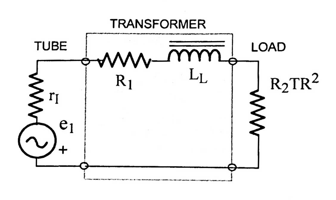
This is a simple low-pass LR filter and the upper -3dB frequency relative to the midband gain is the frequency at which the reactance of the total leakage inductance = resistance of the 3 resistors in series. In other words:
2πfULL = RSER, where LL = LLP + LLSTR2 and RSER = rI + R1 + R2TR2. So...
fU = RSER/2πLL
LLMAX = RSER/2πfU
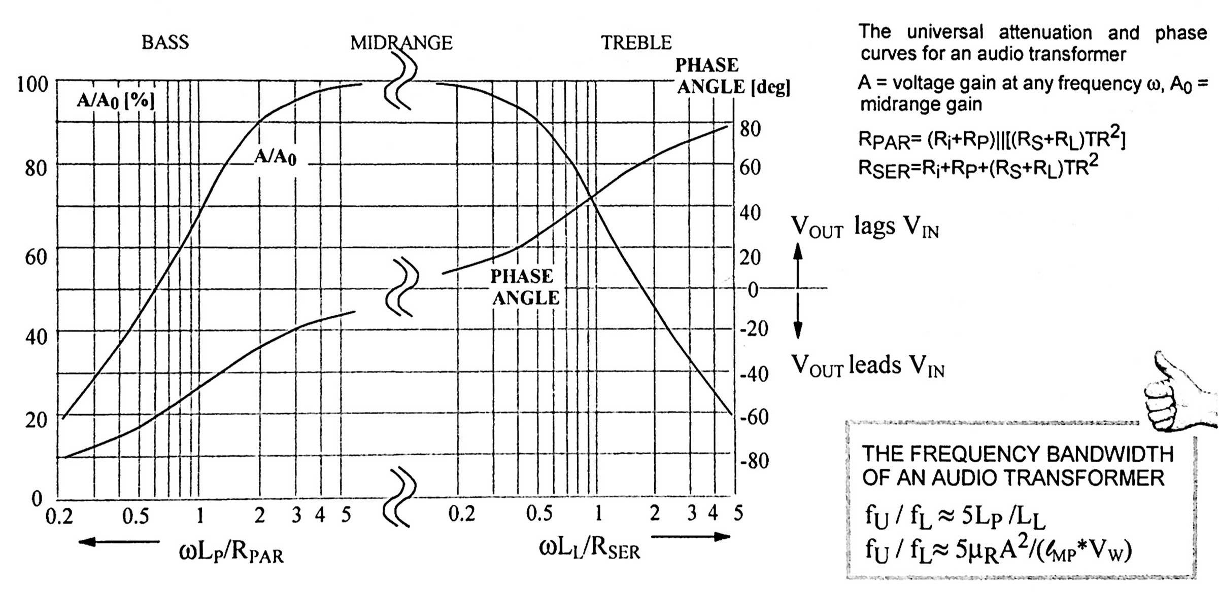
UNIVERSAL FREQUENCY AND PHASE RESPONSE CURVES
It turns out that if you look at values of RPAR and RSER, RSER is usually about (and that's a very big about) 5X larger than RPAR. So, looking at equations above, it's easy to see that:
fU / fL = 5Lp / LL
All the above can be summed up in a graph below, found in Igor Popovich's book "Transformers for Tube amplifiers." Note that for both the high-frequency and the low-frequency halves, the gain has dropped to .707 (1/√2) when ωL = R
LEAKAGE INDUCTANCE
Leakage inductance LL is due to magnetic flux between primary and secondary windings that is not coupled through the magnetic core. If LL = 0, then all of the flux is shared by the windings. A sad fact of life is that as f increases LL increases.
Without going through a derivation (which I don't know anyway), the following expression is given:
LL = u0VNp2/CL2, where V = volume between the windings, CL = coil length, Np = number of turns.
Note that LL is not dependent on the permeability of the iron or the induction levels. LL decreases as the lamination size increases (increasing CL). LL increases with the volume V between the windings, which is partly determined by the insulation thickness. A way to reduce V is to use bulk winding, as opposed to layered arrangements, which decreases the insulation between layers. LL increases quickly as the number of turns increases.
So the opposing goals: increasing NP increases Lp and affords better bass (fL decreases), but it also increases LL which hurts treble (fU decreases).
This can be summed up by the equation at the bottom right of the frequency curve above. This equation is derived as follows:
LP = NP2μRμ0A/ℓMP (see the Transformer Theory page)
LL = μ0NP2VW/A, where VW = volume of the windings (see above).
So, fU / fL = 5LP / LL = 5μRA2 / (ℓMPVW)
This equation shows that increasing cross-sectional area A of the laminations seems to increase the bandwidth, but this is offset by the increase in ℓMP and VW, so the only real way of increasing bandwidth is to increase permeability by using high quality iron.
Looking at the equations for fU and fL, the following is seen:
On the low frequency side, you want to minimize rI and maximize LP.
Unfortunately on the high frequency side you want to maximize rI. This favors pentodes and tetrodes. LP doesn't really matter, but you want to minimize LL.