CHOKE DESIGN STEPS
1. First determine A based on desired inductance and maximum current allowed:
A = 27.5*I*√L
2. Next, calculate NI based on A, using the graph below.
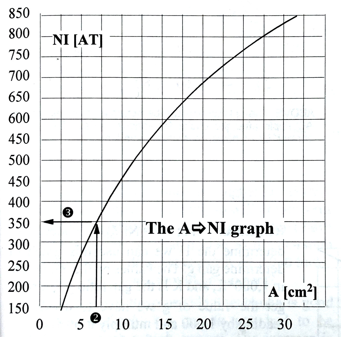
3. Calculate number of turns based on maximum I allowed. For example, in above NI = 350. If Imax = .12ma, then N=2917.
4. Next, figure out if this number of turns will fit onto the bobbin.
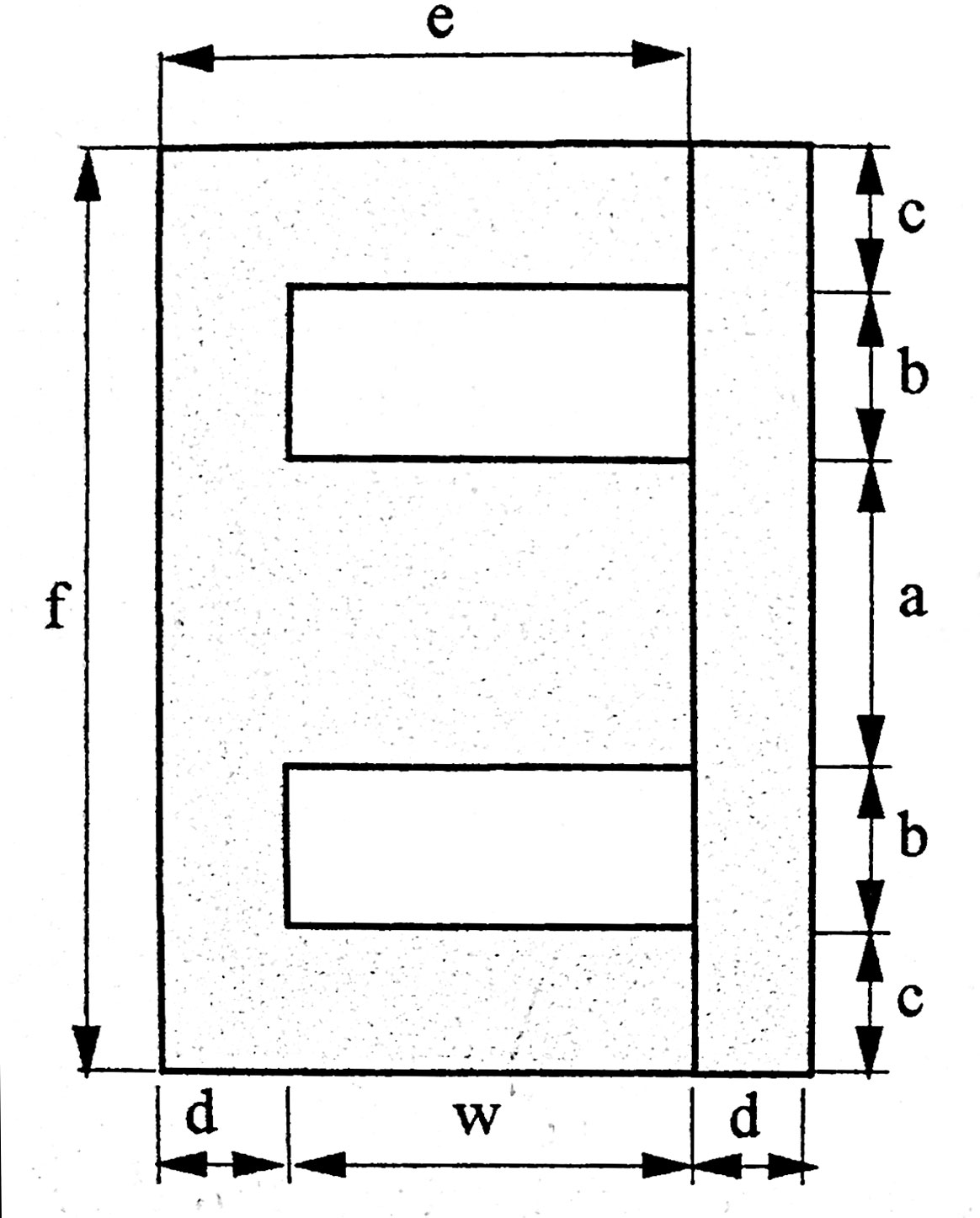

Above are 2 views of an E-I core (no gap shown). The area marked WH x WL is the area where the wires have to fit. Note that this is also b x w. The bobbin has thickness BT(usually about 2mm). On top of the wires is a top insulation layer and a top clearance (usually about .5mm for both)
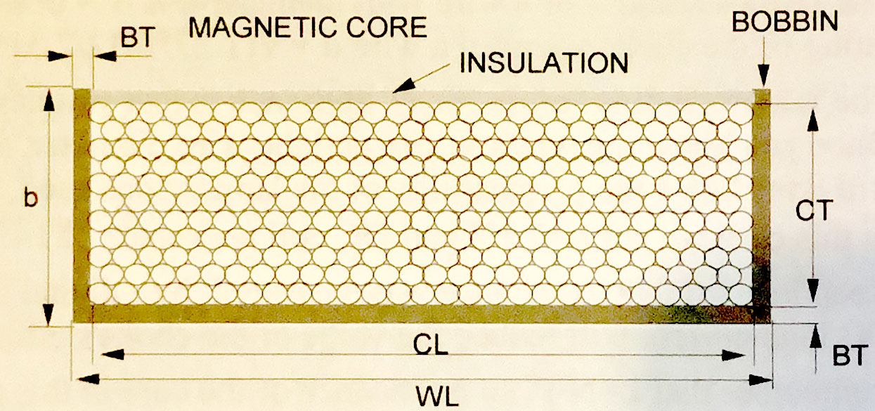
So the coil thickness CT = b - BT - .5mm.
and the coil length CL = w - 2BT
The net winding area NWA = CT * CL
Now
d = diameter of wire in mm, and this should be published.
d+.02 = width of wire with insulation
So GA = (d+.02)2 = area of wire if you assume wire is square, which it isn't, BTW.
If the wire diameter WITH insulation is published, then you don't need to add the .02mm.
Assuming square wire, you can fit the following number of turns in the net winding area NWA:
NN = NWA / GA
NR is the realistic number of turns that can be fit into the NWA and is determined by skill of winder.
NR = .9 * NN for a skilled winder, .8 or .7 is used for less skilled winder.
EXAMPLE:
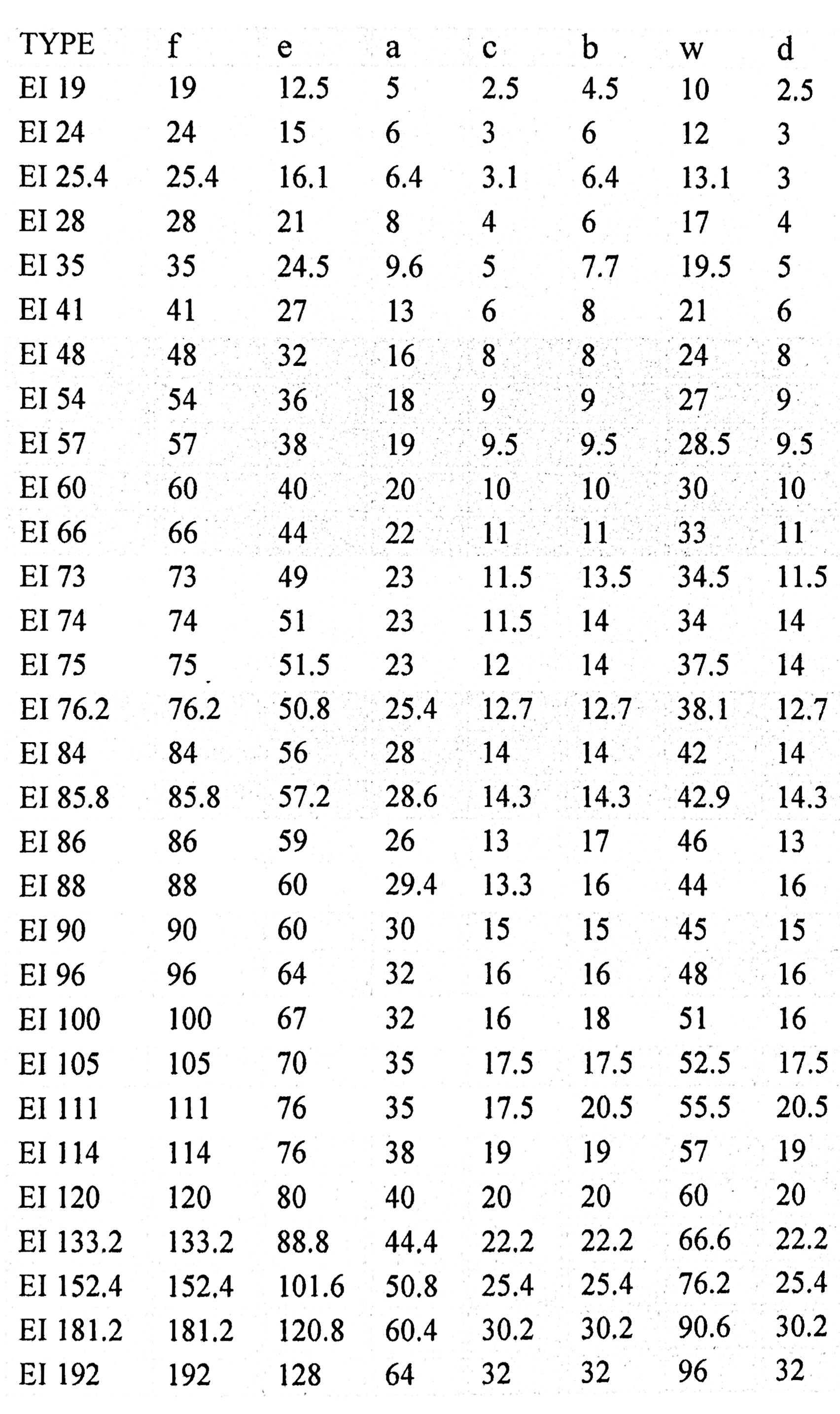
You are using EI60 laminations, so from above table
w=30mm and b=10mm. Assuming bobbin thickness of 2mm ->
CL=30 - 4 = 26mm and CT = 10 - 2 - .5 = 7.5mm, so
NWA = 26 * 7.5 = 195mm2
You have wire with diameter .25mm, and you assume an insulation thickness of .02mm, so
GA = .272 = .073mm2
NN = 195/.073 = 2671 turns.
Assuming a semi-skilled winder
NR = .9*2671 = 2404 turns.
Next, figure out the total length of wire. This will allow a calculation of the resistance R of the inductor. The MLT is the mean length of a turn, so multiplying this by the number of turns should give the total length of the wire
LW = MLT * NR
The formula for MLT, for chokes is
MLT = 2/(a+S+4*BT) + π*CT, where S=stack thickness and other variables were described above.
So in the above example, if the stack thickness is say, 25mm,
MLT = 2/(20 + 25 + 4*2) + π*7.5 = 129mm
We can now figure out the resistance of the length of wire:
First, calculate the total length of the wire
LW = MLT x NR = 2404 x 129mm = 310116mm = 310.116m
RC = ρ * LW / πr2, where, from above, r = d/2 = .125mm = .000125m and ρ = resistivity = 1.68 X 10⁻⁸ Ω-m for copper.
RC = 1.68 x 10⁻⁸Ω-m x 310.116m / π(.000125m)2 = 106.1 Ω
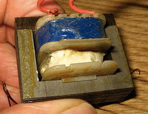
This is a nearly finished E-I transformer. A bobbin with wire wound around it is fit onto the center leg of the E-piece, then the stack of I pieces (darker brown in photo to the left) is put in place.
The Magnetizing Force or Magnetic Field Strength H is defined as:
(1) H(t) = i(t) * N / ℓMP where N=number of turns, ℓMP = mean magnetic length, described below
The flux density B is the Magnetizing force H multiplied by the permeability μ of the core, where μ = μR*μO
μR = relative permeability = 1 for air, much higher than 1 for ferromagnetic materials.
μ0 = absolute permeability = 4π*10-7, so
(2) B(t) = μR*μOH(t)
Magnetic flux Φ is the flux density B x the cross sectional area A of the core.
(3) Φ(t) = B(t) *A
(4) Φ(t) = μR*μOH(t) * A
(5) Φ(t) = μR*μO*i(t)*N*A/ℓMP
Now the induced voltage is proportional to the derivative of the flux Φ(t) and is negated.
V(t) = -N * dΦ(t)/dt
Using equation (5):
V(t) = -N2AμR*μO/ℓMP * di/dt
Now, this is the familiar inductance equation with:
(6) L = N2AμR*μO/ℓMP
For any sinusoidal wave,
(7) Φ(t) = Φmaxsinwt
As in equation (7), V(t) can be expressed as V(t) = Vmax*sin(wt), or alternatively
(9) V(t) = -Vmax*cos(wt)
Comparing (8) and (9), we see that
(10) Vmax = wNΦmax
From equation (3)
(11) Φmax = A * Bmax
so, combining (10) and (11)
(12) Vmax = wNABmax = 2πfNABmax
Rearranging (13), can give the turns per volt (TPV)
(14) TPV = N/Vrms = 104 / (4.44fNABmax)
SPECIAL CASE FOR E-I LAMINATIONS:
For E-I laminations:
(15) TPV = k/AEF, where k is a published number:
50Hz: k=45, GOSS k=40
60Hz: k=37.5, GOSS k=33.3
Rearranging:
k = TPV * AEF
Substituting equation (14) and using AEF for A :
(16) k = 104 / (4.44fNBmax)
ELECTRICAL ANALOGY
Recalling equation (1), for DC it is
(17) H = NI/ℓMP
Now, NI is called the magnetomotive force (MMF) or ampere-turns (AT). It is also called the total field. It is analogous to voltage in an electrical circuit. It is what pushes the flux Φ through the core. This can be expressed as:
(18) MMF = Φ * R, where R is called the reluctance.
Figure out what R is:
Rewriting equation (18) => R = MMF / Φ = NI / Φ
Substituting equation (5) gives:
R = NI / (μINA/ℓMP) where μ = μR*μO
(19) R = ℓMP/μA
So high-permeability materials have low R, so the core presents a low magnetic resistance to magnetic flux, thus very little flux excapes the core into the surrounding air, which has a very high reluctance.
The inverse of reluctance R is called the permeance P and is the inverse of R:
(20) P = μA / ℓMP
Looking at equation (6), it is easy to deduce that:
(21) L = N2P
THE GAP
Without looking at all the hysteresis curves and permeability curves, suffice it to say that DC current through the core as in a choke or SET output transformer leads quickly to saturation of the core. So an air gap is placed to increase the reluctance. Air has a permeability of 1. The grueling calculations are below.
From equation (19):From (18), and remembering that MMF = NI
NI = Φ(Rg + Rc)
= Φ[g/(μOAg) + ℓMP/(μRμOAc) ]
= Φ/A *[g/μO + ℓMP/(μRμO) this assumes Ac=Ag, which is not exactly correct because of fringing.
= B*[g/μO + ℓMP/(μRμO) from equation (3)
Divide both sides by ℓMP and remember that H = NI/ℓMP you get:
H= B * [g/(μOℓMP) + 1/(μRμO)]
From equation (2) H = B * 1/μ, so......
H = B * 1/μEF, where
1/μEF = 1/[g/(μOℓMP)+ 1/(μRμO)]
Things get a little easier for chokes (or transformers) with a gap. A typical μRμO for the core may be in the neighborhood of 10,000 while the μ for the gap is 1. For, say, EI66 laminations, a typical gap is .15mm and a typical ℓMP is maybe 12cm and A=6.8.
So, from equations (22) and (23),
Rc = 12/(10000*6.8) = 1.77x10⁻⁴
Rg = .15/6.8 = 2.2x10⁻³
So the reluctance Rg of the gap is 12 times the reluctance of the core, so is the overwhelming determinant of total reluctance.
EXAMPLE
Assume EI66 lamination with 31mm stack thickness. From chart a=22, so A = 3.1*2.2=6.8cm2. The magnetic path length ℓMP, as calculated way above is 12.25cm. The core has μ = 10,000 and the gap g = .15mm.