LESS COMPLICATED KT-90 PUSH-PULL AMPLIFIER
15Oct2018
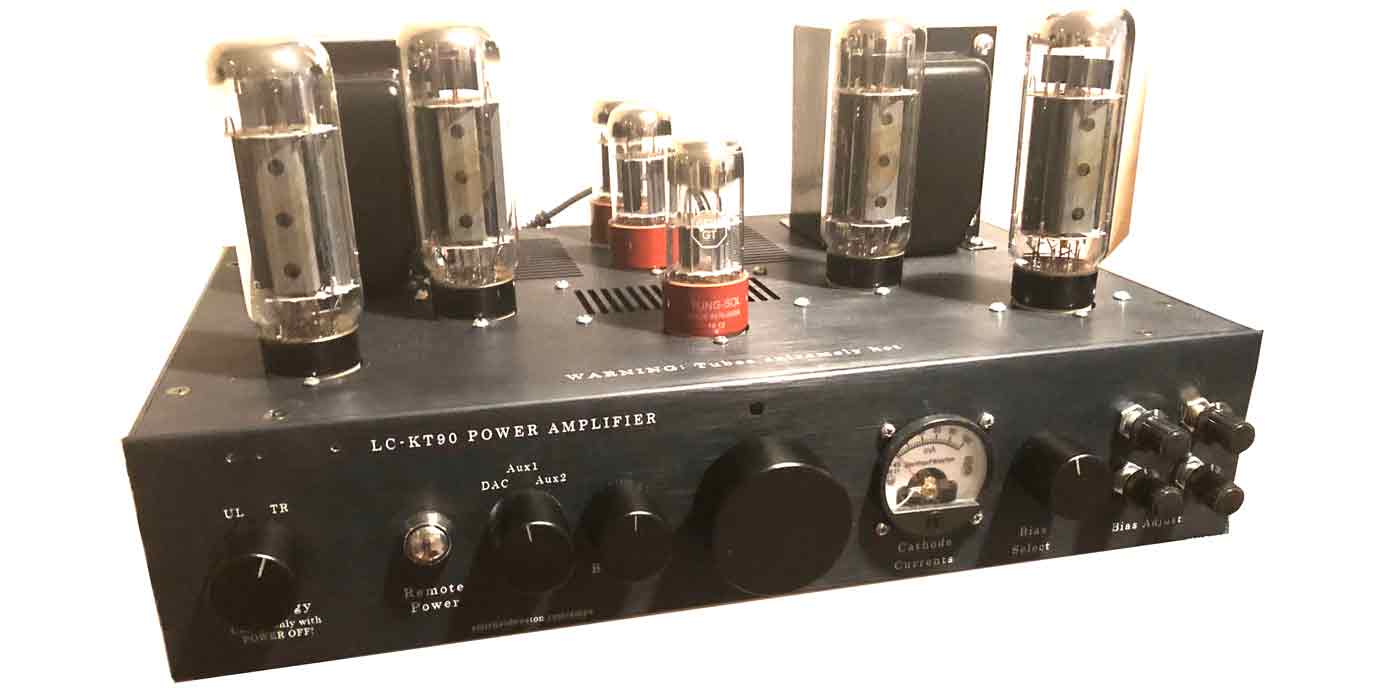
This is my 5th push-pull amplifier, and the LC in its title means "Less Complicated;" It will be the last for a while using this particular topology. The audio portion of the design is almost identical to Ben's Unnecessarily Complicated Push-Pull Power amp, but the power tubes are a little more powerful - KT90's. It is switchable between ultralinear mode and triode mode with a set amount of feedback (12dB)
The power supply is essentially the same, employing a capacitor multiplier to smooth out the ripple in the 500V power tube rails, and a voltage regulator to supply a regulated 400V to the driver circuits. The negative voltage is taken off the power transformer and is around -75V after rectification and smoothing with a capacitor multiplier. Four potentiometers are adjusted, one for each power tube, to set the cathode current to 60ma per power tube.
The accessory circuitry is far simpler (and probably more reliable) than the previous amps. There is an arduino microcontroller (actually a Teensie 3.2) but its only function is to control the soft start functions and to control the remote control on-off and volume. There is no LCD screen.
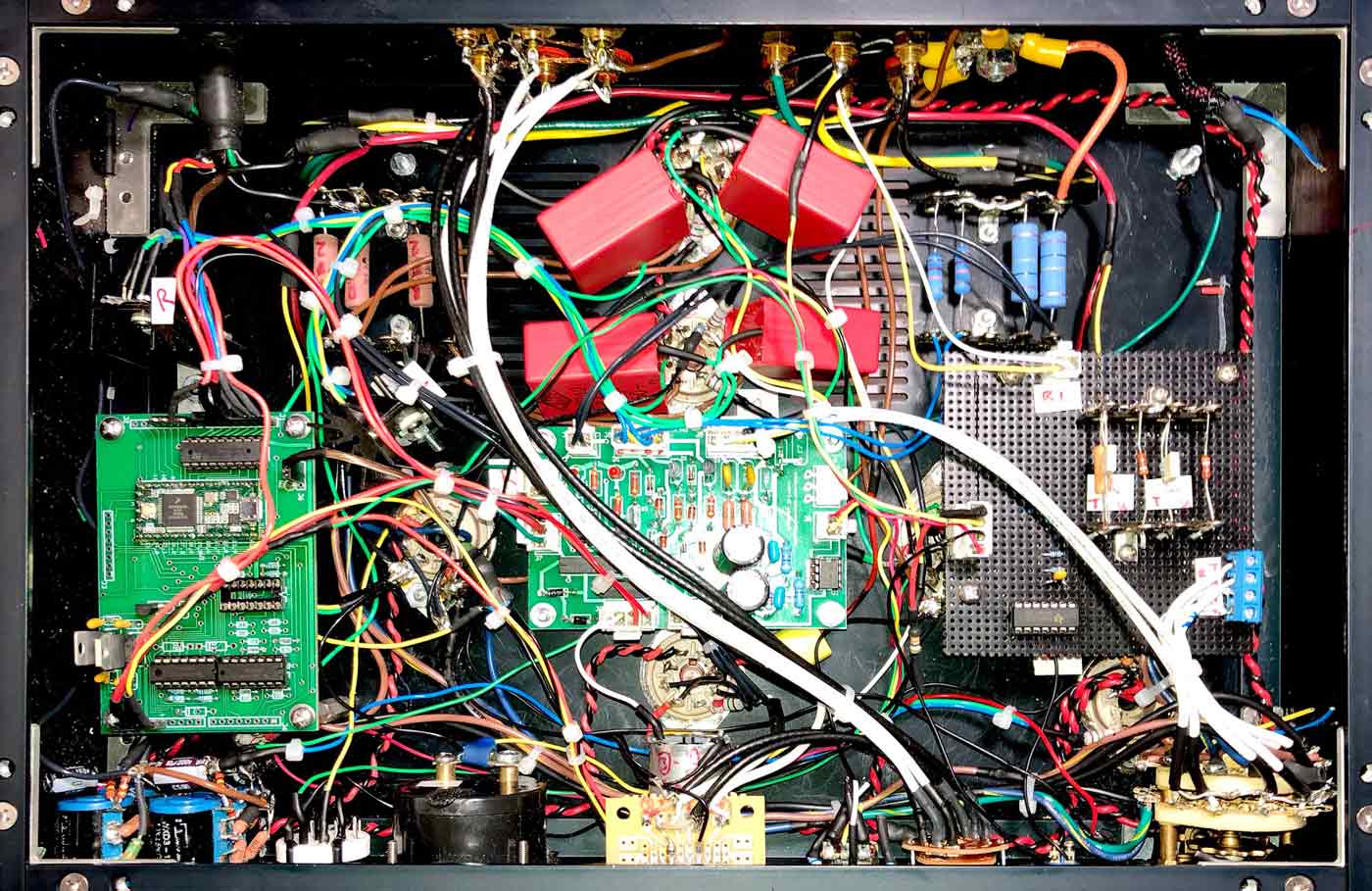
The interior of the amp is shown below. The green Teensie microcontroller board is to the left, the driver board for the input amplifier is the board in the center, and the feedback resistors and caps are on the board to the right. In the lower left corner are the 4 100K potentiometers to control bias, and the ugly orange blocks are the coupling capacitors between the input amplifier and the power stage.
POWER STAGE
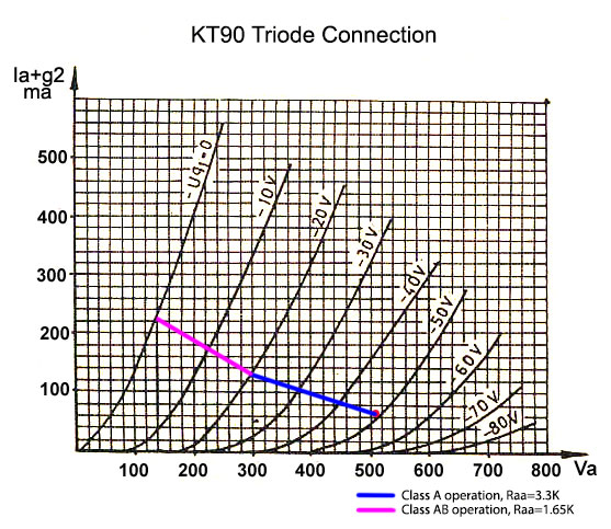
The characteristic curves for a KT-90 power tube, both Ultralinear and Triode mode, are shown below. The operating point will be at Va=500V and Ia = 60ma, for an idle dissipation of 30W, well under the maximum of 42W. The operating points are indicated by the red dots. Class A operation is shown by the blue line and corresponds to an Ra-a = 3.3K (1/2 of the transformer Ra-a of 6.6K.) Class A operation ends when Ia hits 120ma (2 X 60ma), because this means that Ia goes to zero when the sine wave goes maximally negative. Class AB operation is indicated by the purple line and ends when the grid voltage hits 0V (grid current begins to flow). The bias voltage, from the curves, is around -52V for ultralinear and -62V for triode.
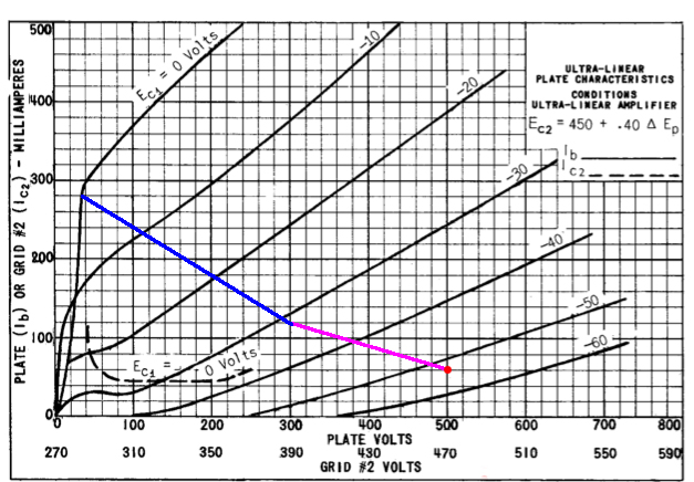
POWER CALCULATIONS:
Class A1 operation (Ultralinear and Triode): P = .5 * Ia2 * Ra-a = .5 * .062 * 6300 = 11.3W
Class AB operation (Triode): P = [2*(500-140)/]2 / Ra-a = 39W
Class AB operation (Ultralinear): P = [2*(500-38)/]2 / Ra-a = 65W
So the amp can theoretically produce 65W in ultralinear, 39W in triode. In actual measurements, the amp doesn't get this nearly this much power before unacceptable distortion occurs. However, 50W should be attainable in ultralinear mode.
INPUT STAGE
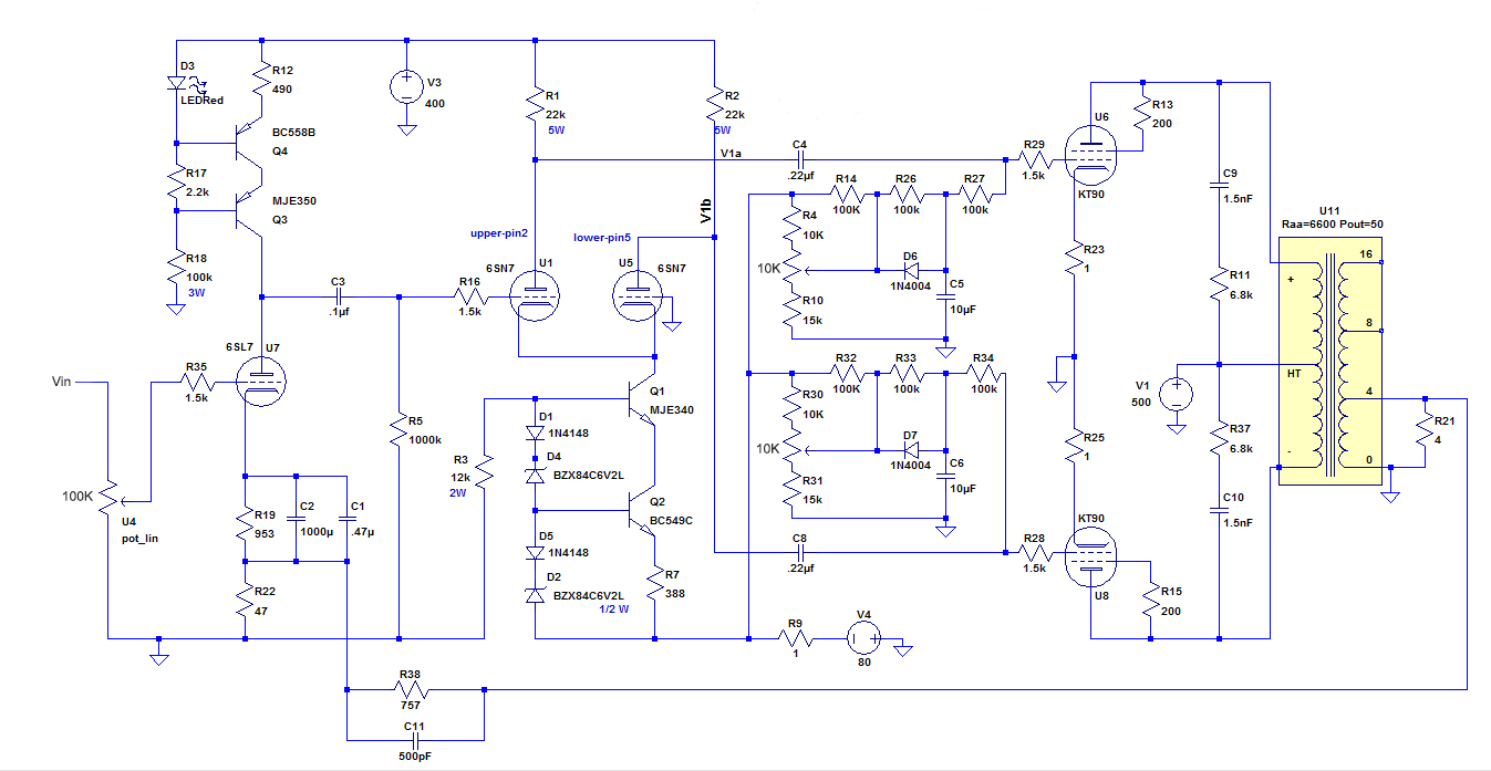
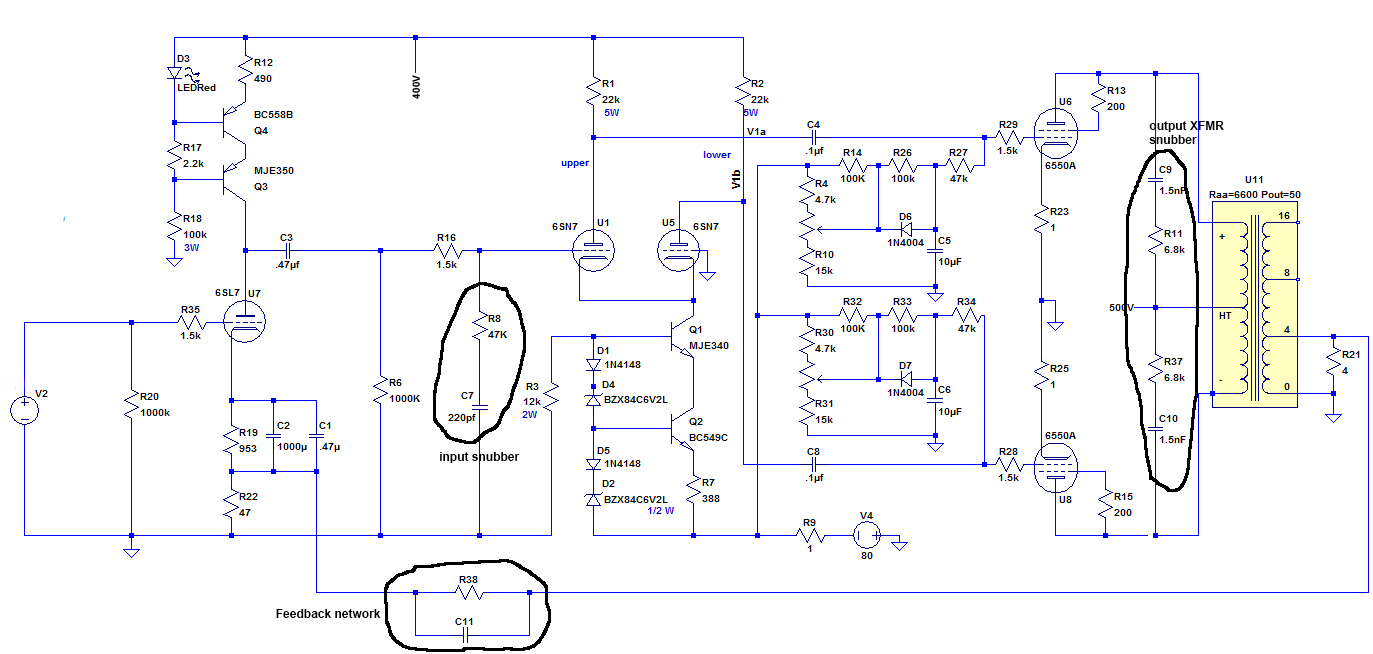
The input stages are completely unchanged from Ben's Unnecessarily Complicated amplifier. The grisly details can be seen on that page. The schematic for the amp is below. The input stage is the left half, the bias circuitry is in the middle (starting with the 10K potentiometers), and the power stage and transformer is to the right.
FEEDBACK
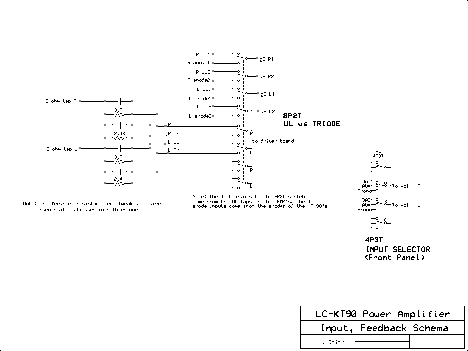
Feedback is much simpler on this amp. Only one choice is given for either mode of operation: 12dB. The schema for feedback is shown below. A 2- position switch on the front switches between ultralinear and Triode mode. The values of the resistors were determined mathematically. I wrote an excel spreadsheet which does the calculations. The values of the capacitors were determined empirically as described below in the section on feedback compensation.
BIAS CIRCUTRY
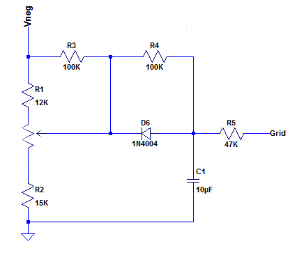
The power tubes will require about -53Vdc applied to each grid in ultralinear mode and around -60Vdc in triode mode. The bias circuit for each tube is shown here. These will be point-to-point wired so no PCB is necessary.
The bias for each power tube will be controllable from the front panel of the chassis by 4 100K potentiometers, shown as U1 in the schematic.
The bias controls the anode current as well as the screen current. Cathode current, an OK proxy for anode current is measured across the 1-ohm cathode resistor.
THE MICROCONTROLLER
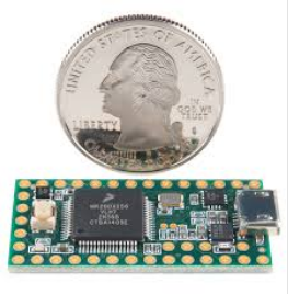
This is the little microcontroller I now use in place of the Arduino. You can see how I ended up with this microcontroller by checking out the "Ben's Unnecessarily Complicated Amp page.
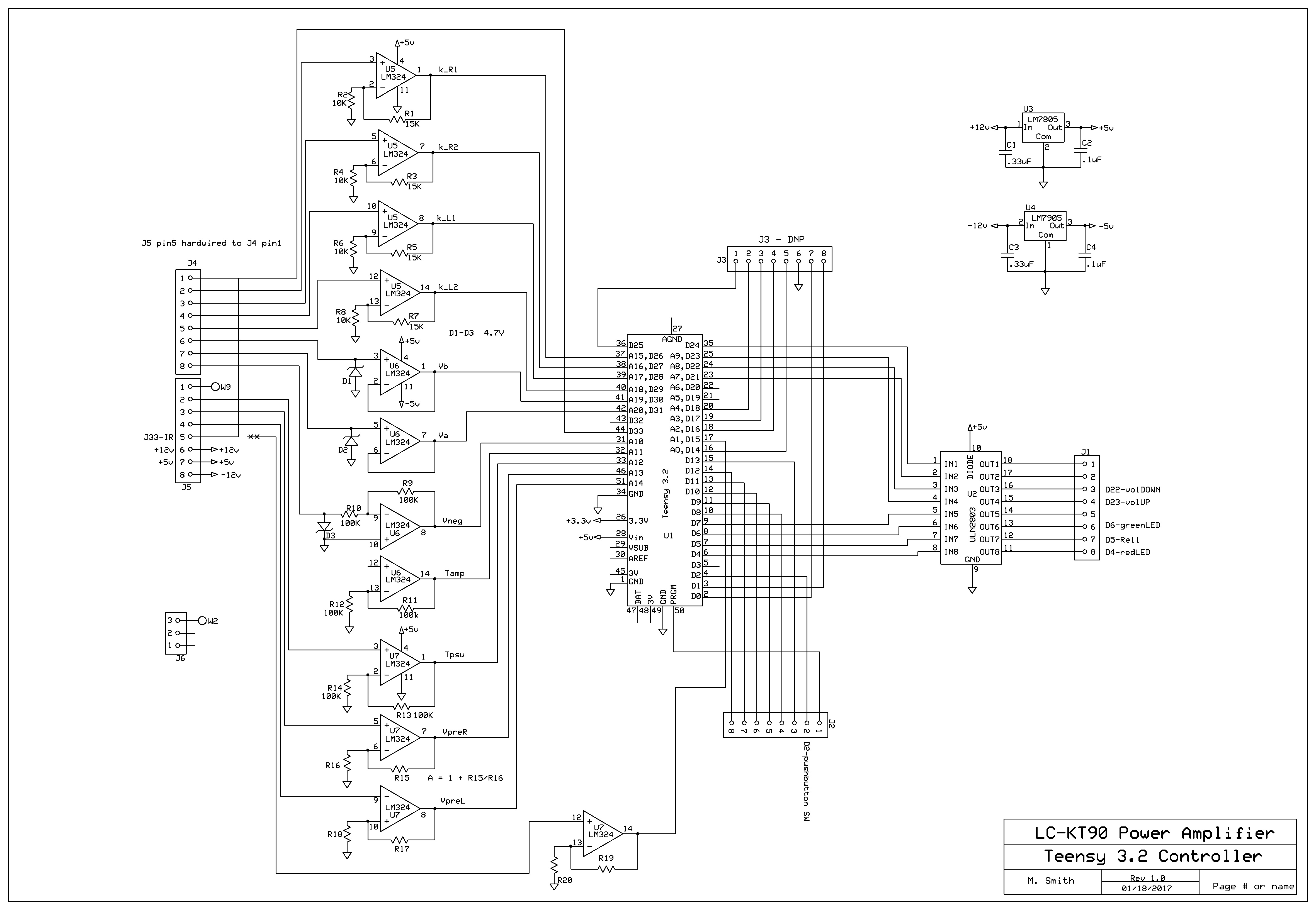
I designed an all-purpose PCB to accomodate the Teensie 3.2 with 16 inputs running through op amps and 8 buffered outputs. This was used in all its glory in the Unnecessarily Complicated 6550 Power Amp. For the Less Complicated Amplifier, only one input was used (from the IR remote) and only 5 outputs were use, 3 to control the soft-start relays and LED's, and two to control the volume. This is shown below.
POWER SUPPLY
The power supply consists of the transformers and rectification sitting in its own chassis plus a voltage regulator and smoothing circuitry sitting in the amplifier chassis. The power supply chassis is connected to the amplifer chassis by an 8-conductor power cable and a 4-conductor cable. Below is the schematic for the circuitry in the power supply chassis.
In the upper portion of the diagram are the relays controlled by Rel1 and Rel2 inputs. These signals come from the Teensie microcontroller and provide for a "soft start". Relay 1 turns on first and sends 115V AC to the power transformers, but through a huge 12R resistor. After a few hundred milliseconds, Relay 2 turns on and sends 115V directly to the transformers. At this point relay1 is turned off.
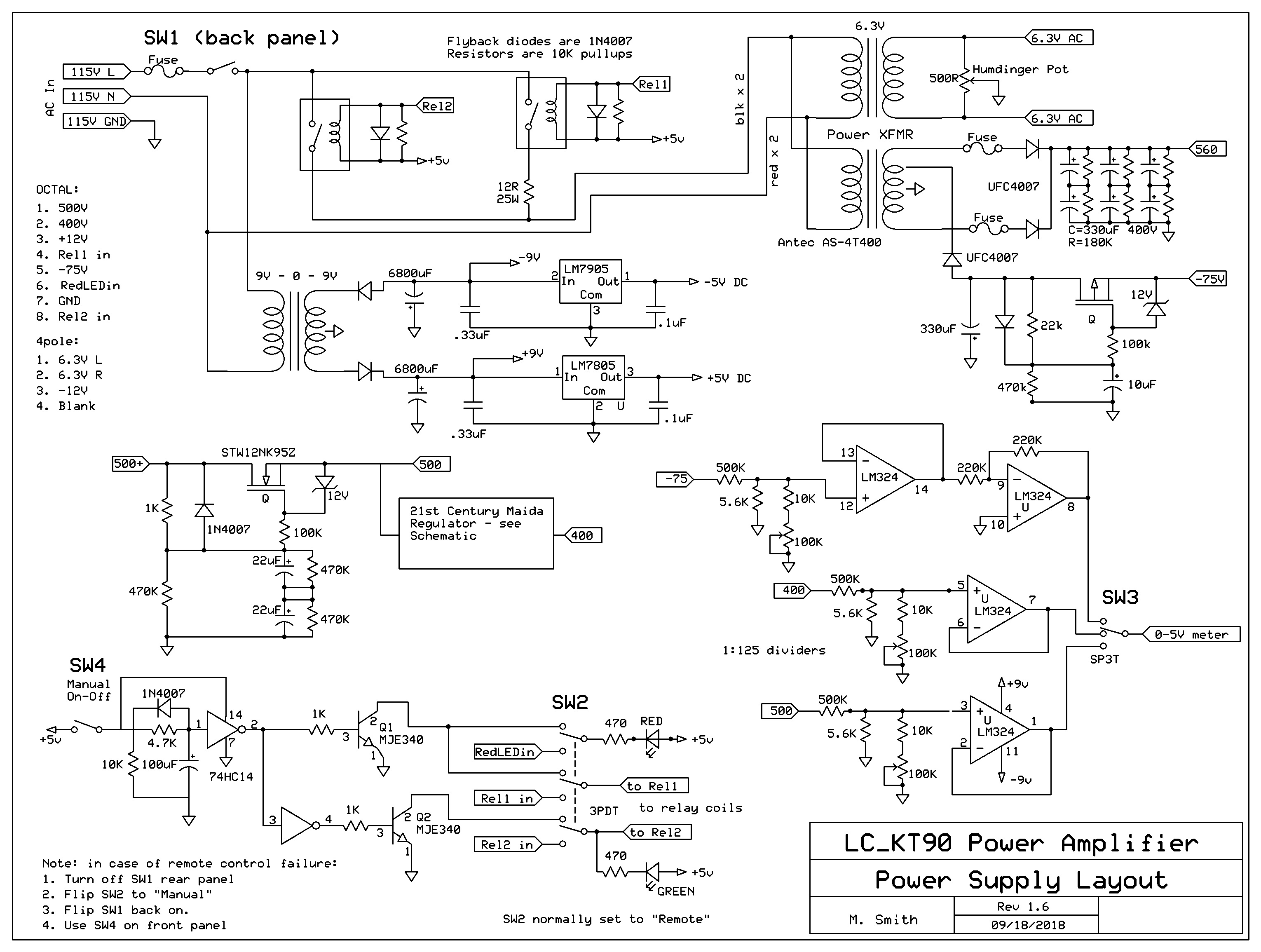
After rectification, 550V and -80V are smoothed by capacitor multipliers, shown above with MOSFET pass elements. A 400V Maida regulator is used to produce a 400V rail for the input stages. 6.3V AC is taken off the power transformer. Finally +12 and -12V (incorrectly labeled as +/- 9V) are taken directly off the rectifier caps. +/-5V are produced by the 7805 and 7905 IC regulators for use in the power supply chassis itself. All these different voltages are sent to the amplifier chassis with the power cables.
A little different twist is the use of Switch 2 (SW2) shown at the bottom of the diagram. Under normal operation, SW2 is set to the "remote" setting, so on-off functions are controlled by the Teensy microcontroller via the IR remote. However, if SW2 is on the "manual" setting (the setting shown in the schematic), on-off is done with a manual switch (SW4). The circuitry between SW4 and SW2 provides the soft-start that would otherwise be done by the microcontroller. This means the amplifier can still be used even if the microcontroller craps out.
The soft-start circuitry works as follows: When SW4 is flipped on, the 74HC14 (a Schottky inverter) is powered on. There is no input (logical "0"), so the output is logical "1", i.e. 5V. This turns on Q1 which allows current to flow through the red LED and through Relay 1, turning them both on. Note that the signal to Q2 is the opposite to that of Q1 because of the second inverter, so Relay2 is forced OFF. After a few hundred milliseconds (determined by the 4.7k resistor and 100uF capacitor, the input to the first inverter becomes logical "1" as the 100uF cap charges. So the output of the first inverter is logical "0", so Q1 is turned off, while Q2 is turned ON. This energizes relay2 (and the green LED) and the amp is officially on. Yay.
COMPENSATION NETWORK
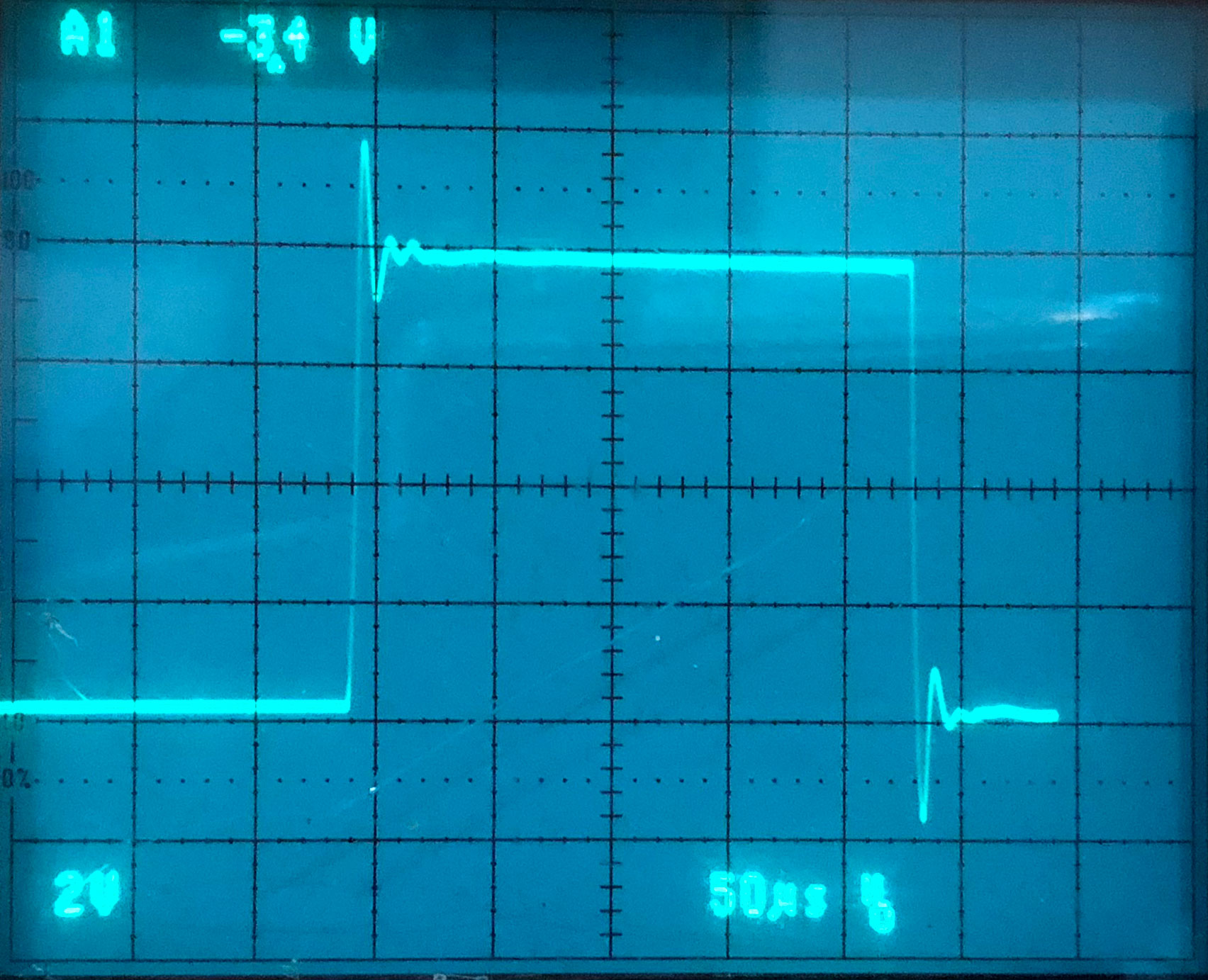
Below are the left channel square responses of the LC-KT90 with feedback resistors in place for both triode (left image) and ultralinear modes. There is significant ringing as expected. The right channel is not shown because it is identical. This ringing means that the amplifier could be unstable at high frequencies without compensation networks put in. All compensation networks are designed to attenuate gain at high frequencies.
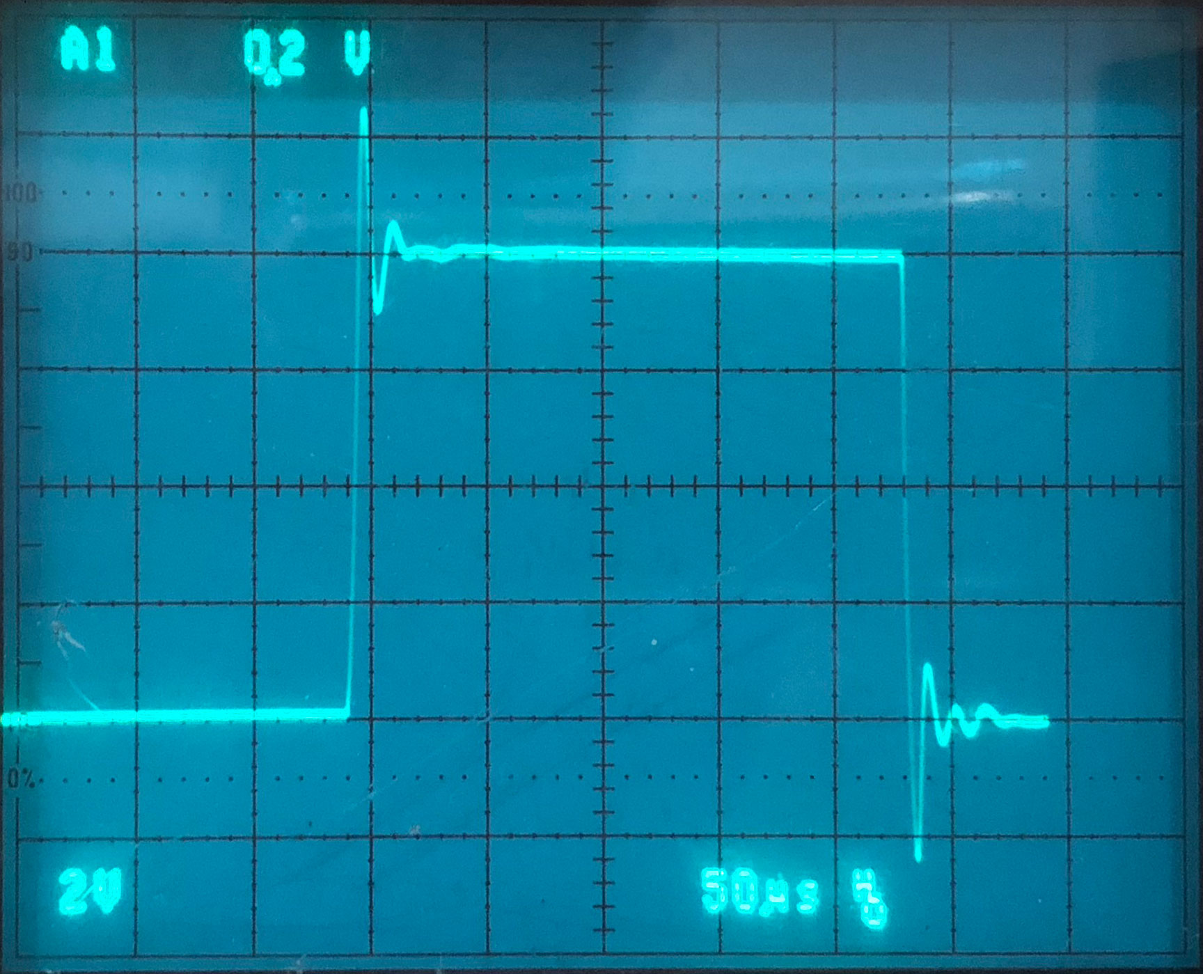
Below is the entire amp with the compensation networks circled. The method I used was taken from a great article by Tim E. Smith on angelfire.com entitled "Empirical implementation of global negative feedback."
The first compensation network is at the output transformer. The technique is taken from Radiotron Designer's Handbook, 4th edition from the 50's. It recommended a resistor value equal to the Ra-a of the transformer. So 6.8K was close enough. C = 1/(100000*Ra-a) = 1.5nF.
The next snubber is at the input to the differential amplifier. The values for R and C are derived entirely empirically. I adjusted a 100K potentiometer and a variable capacitor to eliminate the ringing with the least amount of high frequency attenuation. The optimum values that seemed to work with the triode setting at both low and high feedback settings were R=10K and C=220pF.
Finally, a capacitor is placed across the feedback resistor itself. Remember that there are 2 feedback resistors per channel, one for triode mode and one for ultralinear mode, selectable by the mode switches as shown above on the "Input, Feedback Schema" diagram. The capacitor for each resistor is adjusted until the desired effect is achieved. The idea here is to reduce the reactance of the feedback network at high frequencies, thereby increasing the feedback and reducing gain.
The results of the adjustments would be shown below, but I seem to have lost the image files, and the amp is now in Brooklyn. Oh well.
DISTORTION MEASUREMENTS
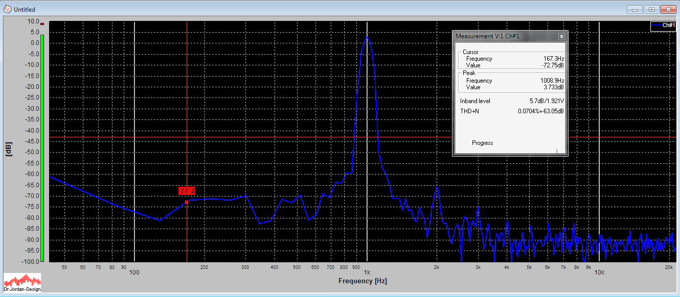
The amp was tested using WinAudioMLS which is a software program that utilizes a high-quality sound card and a computer. It generates FFT's (fast fourier transforms) and analyzes them for distortion. Below is the amp under test.
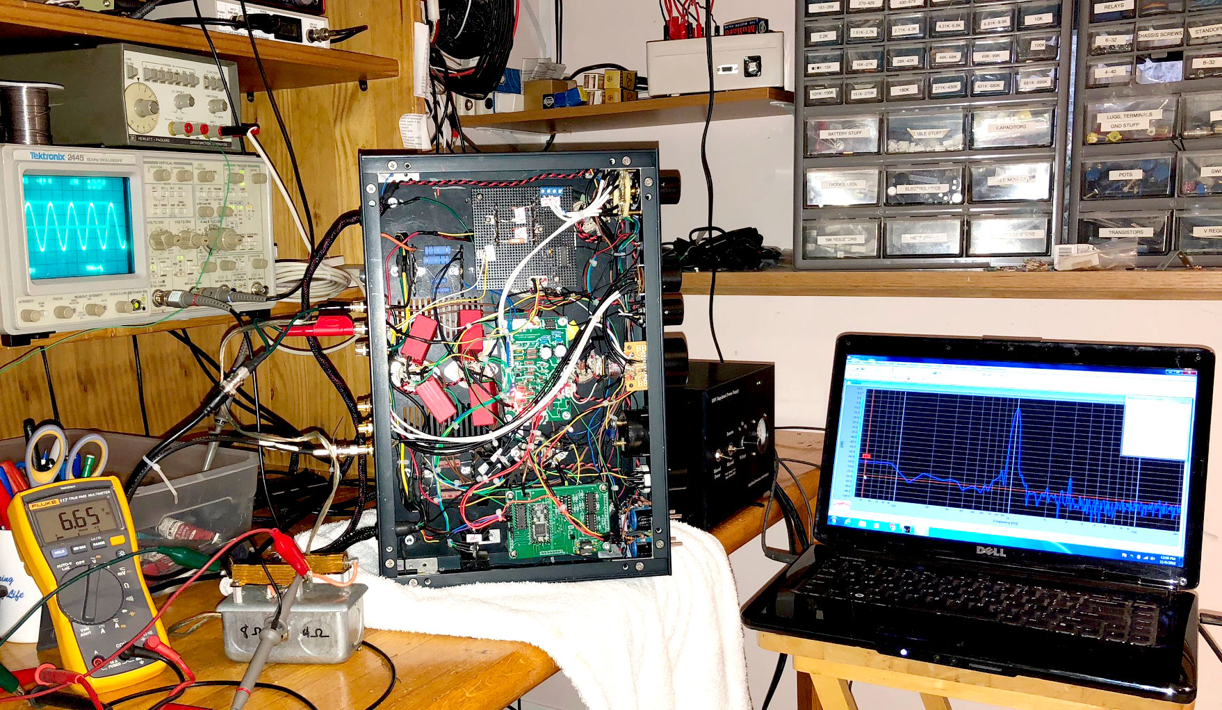
The FFT's (fast fourier transforms) for the left channel are shown below. The right channel was identical and not shown. Note that the distortion (THD+N) is < 0.1% even at very high power. Also, the noise floor is down at -90 to -95dB, which makes the amp DEAD quiet. Note that there is no blip at 60Hz or 120Hz so there is no trace of hum.
TRIODE 30W
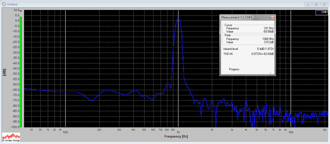
ULTRALINEAR 50W