MIKE'S SIMPLIFIED TRANSFORMER THEORY
The following information is based on building transformers using E-I laminations.
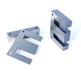
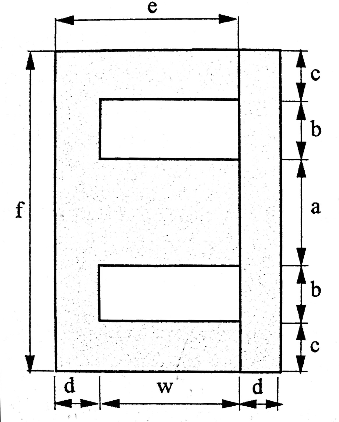
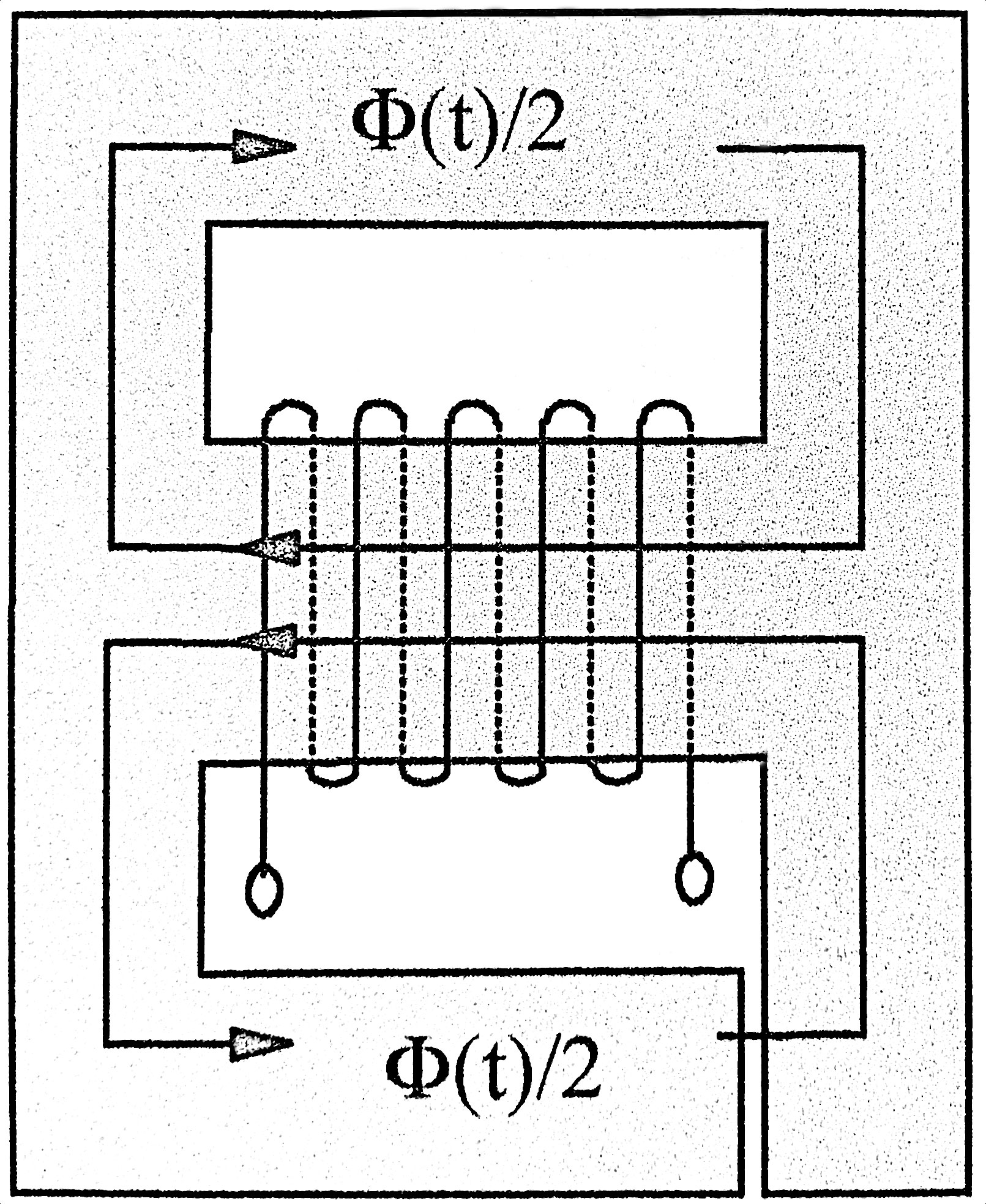
The photo on the left shows E and I pieces individually and stacked to form a core. The center diagram shows the different dimensions used on the E lamination for the table below. To the right. The right diagram shows the flow of flux through the center leg and dividing to flow in the outer legs and then back to the center leg. This is the mean magnetic length discussed below.
The most important dimension is the middle leg width "a". All the other dimensions can be expressed as a product of "a" no matter the size of the laminations:
a a
b .5a
c .5a
d .5a
e 2a
f 3a
w 1.5a
The mean magnetic length ℓMP discussed below is calculated from the table using the following formula:
ℓMP = 2(b+e-d) + πc
Example: for an EI66 lamination:
ℓMP = 2(11+44-11) + 11π = 122.5mm = 12.25cm.
The external dimensions of the finished transformer are as follows. These numbers are increased with bell, mounts, etc.
Height: 3a
Width: 2.5a
Thickness: a+s
THE DOWN AND DIRTY
The Magnetizing Force or Magnetic Field Strength H is defined as:
(1) H(t) = i(t) * N / ℓMP where N=number of turns, ℓMP = mean magnetic length, described below
The flux density B is the Magnetizing force H multiplied by the permeability μ of the core, where μ = μR*μO
μR = relative permeability = 1 for air, much higher than 1 for ferromagnetic materials.
μ0 = absolute permeability = 4π*10-7, so
(2) B(t) = μR*μOH(t)
Magnetic flux Φ is the flux density B x the cross sectional area A of the core.
(3) Φ(t) = B(t) *A
(4) Φ(t) = μR*μOH(t) * A
(5) Φ(t) = μR*μO*i(t)*N*A/ℓMP
Now the induced voltage is proportional to the derivative of the flux Φ(t) and is negated.
V(t) = -N * dΦ(t)/dt
Using equation (5):
V(t) = -N2AμR*μO/ℓMP * di/dt
Now, this is the familiar inductance equation with:
(6) L = N2AμR*μO/ℓMP
For any sinusoidal wave,
(7) Φ(t) = Φmaxsinwt
As in equation (7), V(t) can be expressed as V(t) = Vmax*sin(wt), or alternatively
(9) V(t) = -Vmax*cos(wt)
Comparing (8) and (9), we see that
(10) Vmax = wNΦmax
From equation (3)
(11) Φmax = A * Bmax
so, combining (10) and (11)
(12) Vmax = wNABmax = 2πfNABmax
Rearranging (13), can give the turns per volt (TPV)
(14) TPV = N/Vrms = 104 / (4.44fNABmax)
Another equation, obtained from this source: https://en.wikibooks.org/wiki/Electronics/Transformer_Design
(15) P = .707*J*f*W*A*B, where J = current density, W = window size = w*b
A simplified expression, assuming B=1.2T and f=60Hz is:
(16) A = 1.1129√P
This can be more generalized to:
(16a) A = 55.645√P*B/f
Igor Popovich, in his book, uses very conservative parameters, and uses the following expression to determine the core area based on the transformer's power: He uses:
(16c) A = √P
ELECTRICAL ANALOGY
Recalling equation (1), for DC it is
(17) H = NI/ℓMP
Now, NI is called the magnetomotive force (MMF) or ampere-turns (AT). It is also called the total field. It is analogous to voltage in an electrical circuit. It is what pushes the flux Φ through the core. This can be expressed as:
(18) MMF = Φ * R, where R is called the reluctance.
Figure out what R is:
Rewriting equation (18) => R = MMF / Φ = NI / Φ
Substituting equation (5) gives:
R = NI / (μINA/ℓMP) where μ = μR*μO
(19) R = ℓMP/μA
So high-permeability materials have low R, so the core presents a low magnetic resistance to magnetic flux, thus very little flux excapes the core into the surrounding air, which has a very high reluctance.
The inverse of reluctance R is called the permeance P and is the inverse of R:
(20) P = μA / ℓMP
Looking at equation (6), it is easy to deduce that:
(21) L = N2P
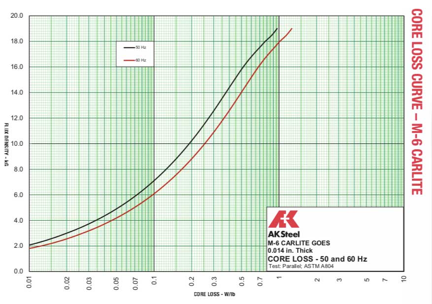
CORE LOSSES